

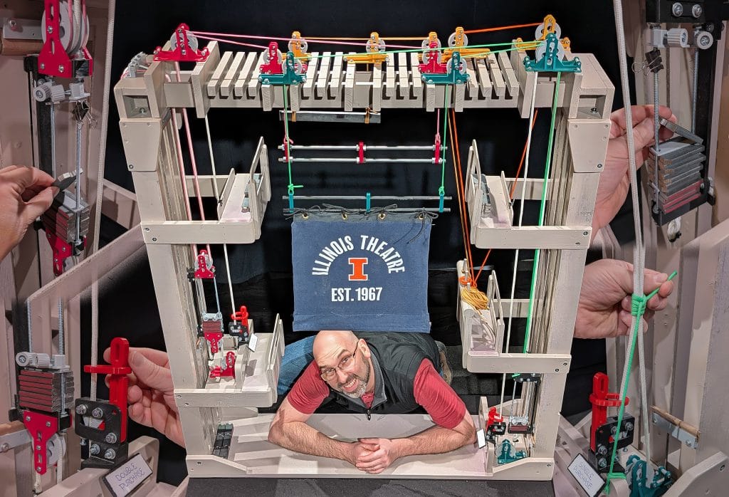
The Kappel Rigging Trainer (KRT) is a functional miniature counterweight system, designed to enable more effective and accessible teaching in the classroom and on stage. Shown above is the first prototype of the KRT, developed during the 24-25 academic year at the University of Illinois Urbana-Champaign. This prototype is built from a combination of commonly available scenic materials, hardware, and custom 3D-printed parts. The frame mimics the cross-section of a typical proscenium-style theater with galleries and a walkable grid. The line sets include a single purchase manual line set, a double purchase manual line set, and a traditional hemp line set. See below for more information!
About the KRT
The Kappel Rigging Trainer was created by Matt Grenier and is named in memory of his personal mentor, Martin W. Kappel (1953-2005). Martin was a devoted husband, father, educator, and a thespian to his core. His professional accomplishments were extensive. On May 31, 2005, Martin’s life was cut short by a tragic accident involving a counterweight rigging system. While working at a local school, lighting equipment was removed from a batten before the counterweight was unloaded from the arbor. The resulting arbor-heavy runaway caused Martin to be pulled off the floor by the purchase line.
Sadly, accidents of this type can happen to anyone, and they are far too common. Of course, the outcome of a runaway varies depending on the exact conditions of the situation. Except in the most severe cases, these accidents are not widely reported. Still, many of us working in the industry have a story, or know someone who has a story, about a counterweight system runaway.
Even with industry efforts to move toward motorized rigging, the reality is that manual counterweight rigging remains prevalent and will be for a very long time. It is therefore incredibly important that effective training be available to students and working technicians. There are problems that inhibit the delivery of such training, the first of which is access to a rigging system. This is why the Kappel Rigging Trainer was created; to improve access and retention of information that helps us produce theatre safely. Additionally, the KRT was created with the hope that Martin’s legacy will continue to be one of passionate devotion to theatre education and making magic happen for the audiences coming to see our shows.
To learn more about Martin’s legacy and the development of the KRT, read the feature article in the Fall 2025 issue of ESTA’s Protocol magazine.
Existing Problems
The KRT was developed to address problems that often inhibit the teaching of counterweight rigging. Some of those problems include:
- Qualified educators may not have access to real rigging system(s)
- Students are unable to see all parts of a real rigging system when standing on stage
- Students may have difficulties visualizing how a system works when only looking at pictures or diagrams
- Students may not fully engage with training that is all lecture-based
- Students with accessibility needs may not be able to fully participate in training
- If mistakes are made with a real rigging system, the consequences are high-stakes
How does the KRT address the problems listed above?
- Educators now have a functional rigging system they can use for teaching
- The scale of the trainer allows all parts to be observed at once
- Students can observe the operation of a physical, functional rigging system sitting right in front of them
- Students can engage constructively with the material through hands-on interaction with the rigging system
- Students that cannot physically operate a real rigging system, or ascend to fly floors/weight floors/grids, can effectively do those things with the trainer. Students with visual impairments can physically interact with all the parts of the trainer. Students with color blindness can distinguish between the different color-coded line sets of the trainer. Regarding working with real rigging systems on stage, it is important to emphasize that every person that is well-trained in the parts and procedures can play a critical role in safety oversight for others… even if they are not able to directly work with the rigging system themselves. To take this one step further, rigging educators with accessibility limitations can also use the trainer to deliver effective instruction even if they have difficulties operating or accessing parts of a real rigging system themselves.
- Mistakes are an important part of the learning process; with the trainer, mistakes can be made with very little risk of injury. Problems with comprehension or execution can be more safely identified when students make mistakes on the trainer before making them on a real system.
Design Goals
The creation of a functional, miniature counterweight system for classroom teaching requires seemingly endless factors to be considered. There are many different priorities that can be pursued and trade-offs that can be made. Ultimately, the goals for the first prototype of the KRT were as follows:
- Size the trainer so that it is not too large to still store and transport easily in a school or classroom environment
- Scale and colorize the parts so that they can be distinguished from a distance, even by those with color-blindness
- The parts should look like the real parts (a rope lock should look like a real rope lock)
- The parts should be functional so that they will create behavior analogous to a real system (the rope lock should function like a real rope lock)
- The trainer should include single, double, and hemp line sets for comparison and discussion of the evolution of rope line systems
- The ropes in the system should be relatively easy to install, tension, and adjust trim without needing to fiddle with tying/retying knots
- The prototype should use commonly available materials, hardware, and build techniques
- The custom parts should be 3D-printable on a typical FDM printer using minimal to no supports

How big is the trainer?
4 feet wide, by 4-1/2 feet tall, by 1 foot deep
What is the scale?
The trainer does not conform to a specific scale. The relative size of components is not realistic by design. Rather, the components are sized to optimize visibility and interactivity given the overall form factor of the trainer.
Does it function like a real system?
YES! The trainer functions with behavior that is analogous to a real system. For example, the rope lock cam tension can be adjusted to ensure that the line set will slip and runaway if the set is loaded incorrectly or not secured with a snub knot, axe handle, or Uncle Buddy.
How long did it take?
As of mid-February 2025, approximately 225 hours have been invested in the development of the KRT.
How must does it cost?
The focus of this project has been to develop a working prototype with a minimal budget of around $1,000. A detailed assessment of costs has not been completed. There are many factors that could affect the cost to build a trainer from scratch. As the prototype is revised and refined, a detailed cost assessment will be conducted.
How do I get a KRT for my school/classroom?
See the section titled “Future Plans.” Request information through this Google Form.
What is the frame made out of?
The prototype frame is made out of typical “one-by” Pine used to build theatrical flats. The boards were hand picked for quality and straightness. The arbor tracks are made from strips of tempered hardboard. These materials were chosen to show that the frame could be built using materials and construction techniques commonly used in theatre.
How were the custom parts designed and 3D-printed?
The custom parts were designed using Autodesk Fusion and printed using a Prusa i3 MK3S+ FDM printer. The first prototype parts were printed using PETG filament while the “final” parts were printed using PLA. All parts were printed using the standard 0.4mm nozzle. Most parts were printed with 2-3 shells and 15-20% rectilinear infill.
Why are the line sets color-coded green, magenta, and gold?
These colors can be differentiated from one another with most common types of color blindness.
What hardware is used throughout the trainer?
The custom parts are assembled using #8 machine screws. Many of the parts are designed with cutouts to accept #8 hex nuts. The arbor rods are made from #10 threaded rod. The sheave side plates are spaced apart using 1/2″ or 1″ Nylon spacers for #8 machine screws. The frame of the trainer was assembled using common scenic construction fasteners including brads, narrow crown staples, course drywall screws, and 1/4″ bolts.
What ropes are used?
The lift lines are typical 550 Paracord and the purchase lines are 1/4″ Para-Max parachute cord. The sheaves and arbors are designed to accommodate lift lines up to 1/8″ in diameter and purchase lines up to 3/8″ in diameter.
What are the sheave bearings?
Most of the prototype sheaves do not utilize bearings. The PLA plastic sheave rides directly on a Nylon spacer. The sheaves spin easily when not under load. Under load, it was found that the loft blocks spin easily enough, but the head and floor blocks encountered a little too much resistance. To combat this, those sheaves were redesigned to accommodate small ball-bearings. The next iteration of the KRT will utilize igus engineered plastic sleeve bearings instead of ball-bearings.
How are the counterweights made?
The counterweights are designed to be made from a stick of steel flat bar, up to 1/2″ thick. The bricks were first made from 1″ wide flat bar and then remade at 1-1/2″ wide for improved arbor capacity. To make them, holes were drilled in the bar at regular intervals and then split across the middle using a metal band saw to minimize the blade kerf loss. The corners of the counterweights were chamfered using a stationary belt sander. The bricks are approximately 4oz.
How much weight can you load onto the batten or arbor?
A weight capacity or limitation has not been determined. The arbor capacity is largely limited by the width of the steel flat bar used to make the counterweights. It has been found that approximately 5lbs needs to be placed on the single purchase batten to counteract frictional losses and achieve realistic behavior. The counterweight required to balance the batten load is not truly one to one due to frictional losses.
Why are ladder battens used instead of typical single-pipe battens?
In order to demonstrate the principle of empty batten “pipe weight,” the battens cannot be too lightweight or frictional losses will not be overcome and no counterweight will be needed. A ladder batten is a good excuse to double the empty weight of the batten.
The development of the KRT prototype has included demonstrations and formal classroom teaching. Below are some initial findings:
- Material can be covered efficiently and interactively
- The teacher can stand behind the trainer and be seen through it (depending on what is being flown on the battens)
- With sufficient load on the batten, the behavior of the trainer is analogous to a real system; i.e. the line set will slip and run if it is not secured with a snub line, axe handle, or Uncle Buddy
- Tailored supplemental lecture material is desirable to draw parallels to real world systems (including close-up photos of the trainer parts)
- Classroom setup can be tricky depending on the room, number of students, location of the screen/projector, height of trainer, etc
- Extra 3D-printed assemblies and/or examples of real hardware are useful to pass around the room for closer inspection by students
- There is ample promise for varied teaching methods (direct and constructivist), and exploration of advanced rigging topics

A timeline of project development:
- 09/29/24 – First custom parts designed, 3D-printed, and assembled (the rope lock)
- 10/06/24 – First prototype single-purchase arbor
- 10/15/24 – First prototype sheaves and pulley block
- 10/20/24 – First prototype double-purchase arbor
- 11/20/24 – Finished build drawings and began build of wooden frame
- 11/23/24 – Wooden frame build completed
- 11/24/24 – First “final” parts 3D-printed in color PLA
- 12/01/24 – First counterweights made
- 12/03/24 – Assembly of “final” parts for prototype (rope locks, pulley blocks, arbors, etc)
- 12/04/24 – First prototype “Uncle Buddy” 3D-printed
- 12/04/24 – Installation of 3D-printed parts onto wooden frame
- 12/04/24 – First functional tests and development of loads to hang on battens
- 12/05/24 – Use of trainer prototype to teach introductory lesson to Stagecraft class
- 12/08/24 – First prototype trim clamp for hemp line set
- 12/10/24 – USITT Poster session first-draft slides
- 01/06/25 – Thumb screws 3D-printed for top arbor spreader plates
- 01/06/25 – Sewing miniature curtains, including pleated “Velour” curtain with pockets for steel weights
- 01/07/25 – Breakdown of prototype for painting, installed bolts for easier disassembly later
- 01/08/25 – Painting and clear-coating
- 01/09/25 – Reassembly of prototype in preparation for Illinois High School Theatre Festival (IHSTF)
- 01/10/25 – Demonstration of the trainer at Illinois High School Theatre Festival (IHSTF)
- 01/17/25 – Photographing prototype for documentation and promotion
- 02/06/25 – USITT Poster session final-draft slides
- 02/06/25 – Mock-up of display stand and lighting for USITT
- 02/16/25 – Launch of webpage on MattGrenier.com
- 2/19/25 – Use of trainer prototype to teach hemp rigging in Intro to Stage Rigging class
- 03/06/25 – Display and demonstration at USITT 2025 in Columbus, OH
- 3/31/25 – Use of trainer prototype to teach counterweight rigging in Intro to Stage Rigging class
- 4/8/25 – Promotion of trainer at University of Illinois’ Research Live! speech competition
- 6/30/25-7/30/25 – Extensive redesign and prototyping including reworked sheave bearings, a new European-style rope lock, compartment-style arbors, and variations of the frame made from tab-and-slot CNC-cut parts
- 9/12/25 – Registration of domain kappelriggingtrainer.com
- 9/13/25 – Began design of a metal variation of the frame made from square tube and custom sheet metal parts
- 9/24/25 – Waterjet cut new prototype counterweight from 1/4″ steel
- 10/1/25 – Feature article published in ESTA’s Protocol magazine titled “Introducing the Kappel Rigging Trainer: How a tragedy formed Martin’s legacy.”
- 11/12/25 – Resumed design and documentation work to prepare for next full-scale prototype building
Documentation for the Kappel Rigging Trainer will be released under a Creative Commons BY-SA 4.0 license. Drawings, 3D files, build instructions, and lesson plans will be available for free. Educators will be encouraged to deploy their own KRT and share their findings and improvements with others. The current goal for release of the KRT documentation is spring 2026 by the end of the academic year.
If you have an interest in the KRT or would like to submit feedback, please fill out this Google Form.
Plans for the Future
Implementation of bearings in the sheaves for improved movement requiring less weight
> Design changes completed, ready for testingMiscellaneous adjustments to improve ease of rope reeving, anchoring, and trimming
> Design changes completed, ready for testingAdditional variations of the frame with emphasis on rapid manufacturing via CNC and disassembly for transport
> Design changes completed, ready for testing- Additional variations of the frame to accommodate five line sets instead of just three
> Design in-progress Implementation of a second pin rail for the hemp line set to aid in tying off ropes at separate trim heights
> Design changes completed, ready for testing- Refined designs for demonstration loads to hang from the battens
- Refined/documented design for the hemp sandbag
- Development of companion teaching materials (slides and lesson plans)
- Workshop/session at USITT!
Ideas List
- Functional “chain hoists” that can be used to demonstrate overhauling a batten
- Functional block and tackle that can be used to overhaul the hemp lines
- Version of the trainer that can be collapsed and packed into an ATA flight case
- Miniature elements needed to teach other rigging concepts like motor/truss, arena rigging, curtain systems, etc
Photo Highlights


Video Demonstration
ESTA Protocol Magazine Article
The story of the Kappel Rigging Trainer was featured in the fall 2025 issue of ESTA’s Protocol magazine. The Entertainment Services and Technology Association (ESTA) is a non-profit trade association for the entertainment technology industries.

Research Live!
Research Live! is a speech competition hosted by the Graduate College at the University of Illinois Urbana-Champaign. Graduate students have three minutes to explain their research and its impact to non-experts. The development of the Kappel Rigging Trainer was presented in a speech titled “Teaching Theatrical Counterweight Rigging in the Classroom.” This speech was selected as one of 13 finalists and received the “Storyteller Award.” For more information about Research Live!, visit the Graduate College website. Watch the speech below!

USITT Poster
The Kappel Rigging Trainer was featured in a digital poster session at USITT 2025 in Columbus, Ohio. Use the arrows below to navigate the slides. The United States Institute for Theatre Technology (USITT) promotes dialogue, research, and learning among practitioners of theatre design and technology. “Poster sessions” are a means of publishing and sharing research at national conferences. For more information visit USITT.org.


Development Highlights


Request Information or Submit Feedback
If you would like to request information or submit feedback about the Kappel Rigging Trainer, please fill out this Google Form.
Alternatively, you can contact Matt directly using the contact form.